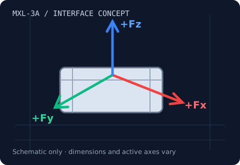
MXL-3A · Fx, Fy, Fz
3-Axis Load Cells
Resolve contact force into Fx, Fy and Fz.
10 N–5 kN family target
Review range & integration →MXL-2D / Fx & Fz, or Fx & Fy
Separate normal force from tangential friction force.
Range & load-path review
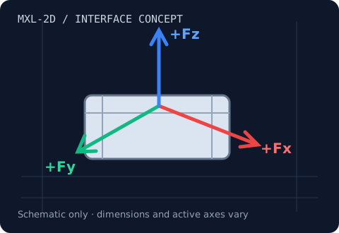
A biaxial load cell measures two specified components. An Fx/Fz arrangement supports normal-load and friction-force testing; an Fx/Fy arrangement measures planar forces. The inactive component is not measured, but its mechanical load still matters for safety and measurement error.
Use cases: Brake friction, cutting-spindle development, guideway resistance testing.
| Model / planning identifier | Fx / Fy shear capacity | Fz axial capacity | Dimensions / interface | Max crosstalk | Overload limit |
|---|---|---|---|---|---|
| MXL-2D-L | 20–200 N target | 20–200 N if Fx/Fz | Custom mounting review | <1% FS design target; validate configuration | 150–300% design target; confirm combined-load envelope |
| MXL-2D-M | 200 N–5 kN target | 200 N–5 kN if Fx/Fz | Custom mounting review | <1% FS design target; validate configuration | 150–300% design target; confirm combined-load envelope |
| MXL-2D-H | 5–50 kN target | 5–50 kN if Fx/Fz | Custom mounting review | <1% FS design target; validate configuration | 150–300% design target; confirm combined-load envelope |
These are requested family targets and planning identifiers, not released model specifications. In an Fx/Fz configuration Fy is not measured; in an Fx/Fy configuration Fz is not measured. Request an approved drawing, axis-specific calibration and combined-load limits before purchase.
One measurement chain
A raw bridge output needs compatible excitation and signal conditioning. Simultaneous sampling keeps rapidly changing axis signals aligned. A calibrated digitizer can apply the correct conversion and present forces in newtons.
Plan two active bridge channels; a third channel may remain unused. Confirm the selected module supports your output, sample rate and latency.
Review USB / PLC / EtherCAT options →Resultant: 111.803 N
Illustrative friction ratio: 0.5000
Ftotal = √(Fx² + Fy² + Fz²). The ratio μ = √(Fx² + Fy²) / |Fz| assumes Fz is aligned with the known surface normal and quasi-static contact. It is not a general surface-angle measurement. Illustrative math only; no live sensor data.
Engineering questions
Two bridge channels are normally needed for two measured axes. A compatible three-channel module can leave one channel unused.
Yes, for an aligned test with a known normal direction and sufficient nonzero normal load. The normal and tangential signals must be synchronized.
We need the exact model revision, mounting drawing, pinout, bridge excitation, calibration and operating load case. Compatibility is confirmed by a configuration-specific review.
MXL-3A · Fx, Fy, Fz
Resolve contact force into Fx, Fy and Fz.
10 N–5 kN family target
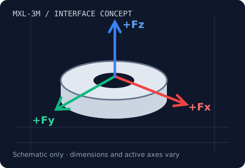
Review range & integration →MXL-3M · Fx, Fy, Fz
Fit three force components into a constrained end effector.
2–100 N family target
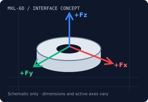
Review range & integration →MXL-6D · Fx, Fy, Fz, Mx, My, Mz
Measure three forces and three moments at one interface.
20 N–10 kN · 0.5–500 N·m family target
Review range & integration →MXL-2D · Fx & Fz, or Fx & Fy
Separate normal force from tangential friction force.
20 N–50 kN family target
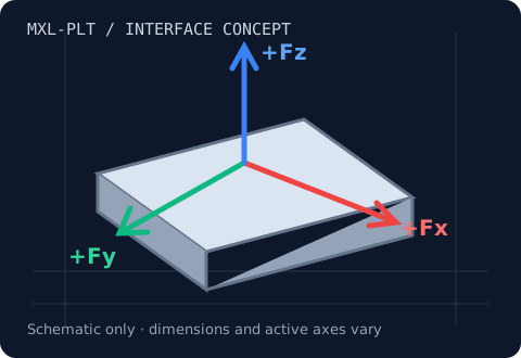
Review range & integration →MXL-PLT · Aggregate Fx, Fy, Fz
Capture distributed forces across a rigid test surface.
5–200 kN per axis family target
Review range & integration →