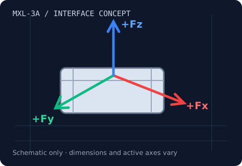
MXL-3A · Fx, Fy, Fz
3-Axis Load Cells
Resolve contact force into Fx, Fy and Fz.
10 N–5 kN family target
Review range & integration →MXL-6D / Fx, Fy, Fz, Mx, My, Mz
Measure three forces and three moments at one interface.
Range & load-path review
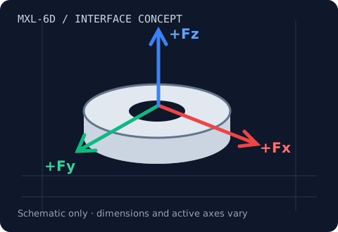
A six-axis load cell provides a six-component wrench: three forces and three moments referenced to a defined origin. MXL-6D targets a calibrated sensor-and-electronics package so the receiving controller can work in engineering units. Matrix version, serial number, reference frame and tool offset must remain linked to the hardware.
Use cases: Cobot and humanoid wrists, wind-tunnel balances, underwater thruster testing.
| Model / planning identifier | Fx / Fy shear capacity | Fz axial capacity | Dimensions / interface | Max crosstalk | Overload limit |
|---|---|---|---|---|---|
| MXL-6D-L | 20–200 N target | 20–200 N target | 0.5–10 N·m moment target | <1% FS design target; validate configuration | 150–300% design target; confirm combined-load envelope |
| MXL-6D-M | 200 N–2 kN target | 200 N–2 kN target | 10–100 N·m moment target | <1% FS design target; validate configuration | 150–300% design target; confirm combined-load envelope |
| MXL-6D-H | 2–10 kN target | 2–10 kN target | 100–500 N·m moment target | <1% FS design target; validate configuration | 150–300% design target; confirm combined-load envelope |
These are requested family targets and planning identifiers, not released model specifications. Moment ranges are separate from force ranges. Footprint requires drawing confirmation. Request an approved drawing, axis-specific calibration and combined-load limits before purchase.
One measurement chain
A raw bridge output needs compatible excitation and signal conditioning. Simultaneous sampling keeps rapidly changing axis signals aligned. A calibrated digitizer can apply the correct conversion and present forces in newtons.
Plan six synchronized bridge channels and the matched force/torque matrix. Confirm the selected module supports your output, sample rate and latency.
Review USB / PLC / EtherCAT options →Resultant: 111.803 N
Illustrative friction ratio: 0.5000
Ftotal = √(Fx² + Fy² + Fz²). The ratio μ = √(Fx² + Fy²) / |Fz| assumes Fz is aligned with the known surface normal and quasi-static contact. It is not a general surface-angle measurement. Illustrative math only; no live sensor data.
Engineering questions
It means three orthogonal force components and three moment components. Moments depend on the selected reference origin.
Only with compatible excitation, synchronous acquisition, the correct calibration matrix and validated conversion software. A supported digitizer can perform the conversion.
We need the exact model revision, mounting drawing, pinout, bridge excitation, calibration and operating load case. Compatibility is confirmed by a configuration-specific review.
MXL-3A · Fx, Fy, Fz
Resolve contact force into Fx, Fy and Fz.
10 N–5 kN family target
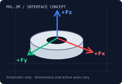
Review range & integration →MXL-3M · Fx, Fy, Fz
Fit three force components into a constrained end effector.
2–100 N family target
Review range & integration →MXL-6D · Fx, Fy, Fz, Mx, My, Mz
Measure three forces and three moments at one interface.
20 N–10 kN · 0.5–500 N·m family target
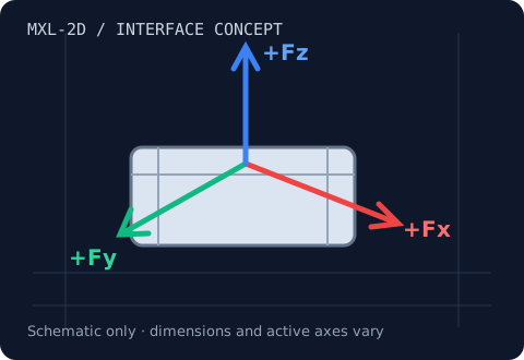
Review range & integration →MXL-2D · Fx & Fz, or Fx & Fy
Separate normal force from tangential friction force.
20 N–50 kN family target
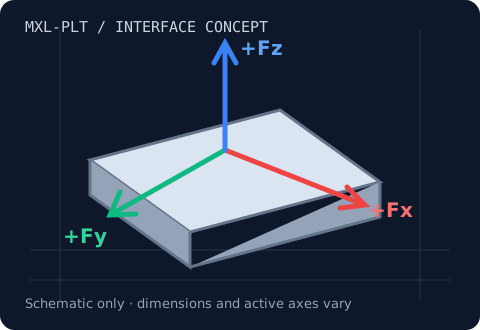
Review range & integration →MXL-PLT · Aggregate Fx, Fy, Fz
Capture distributed forces across a rigid test surface.
5–200 kN per axis family target
Review range & integration →