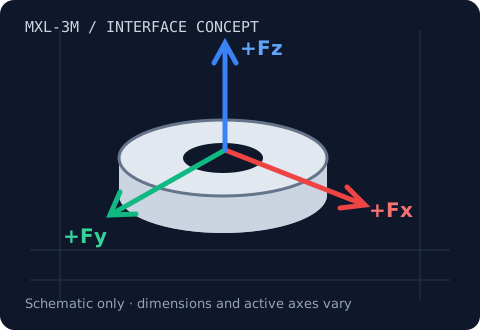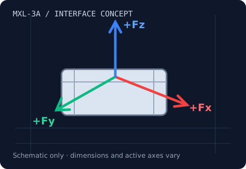
MXL-3A · Fx, Fy, Fz
3-Axis Load Cells
Resolve contact force into Fx, Fy and Fz.
10 N–5 kN family target
Review range & integration →MXL-PLT / Aggregate Fx, Fy, Fz
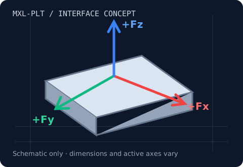
Capture distributed forces across a rigid test surface.
Range & load-path review
A force platform combines multiple sensing locations with a stiff mounting surface. The MXL-PLT concept uses four triaxial sensing points. Total force is the transformed sum of all points; moment and center-of-pressure calculations additionally require sensor coordinates and a validated platform calibration.
Use cases: Landing-gear impact, CNC heavy cutting, biomechanics research.
| Model / planning identifier | Fx / Fy shear capacity | Fz axial capacity | Dimensions / interface | Max crosstalk | Overload limit |
|---|---|---|---|---|---|
| MXL-PLT-L | 5–20 kN platform target | 5–20 kN platform target | 200×200 mm concept | <1% FS design target; validate configuration | 150–300% design target; confirm combined-load envelope |
| MXL-PLT-M | 20–50 kN platform target | 20–50 kN platform target | Footprint to confirm | <1% FS design target; validate configuration | 150–300% design target; confirm combined-load envelope |
| MXL-PLT-H | 50–200 kN platform target | 50–200 kN platform target | Up to 600×600 mm concept | <1% FS design target; validate configuration | 150–300% design target; confirm combined-load envelope |
These are requested family targets and planning identifiers, not released model specifications. Platform ratings are aggregate targets, not a per-corner sensor rating. Request an approved drawing, axis-specific calibration and combined-load limits before purchase.
One measurement chain
A raw bridge output needs compatible excitation and signal conditioning. Simultaneous sampling keeps rapidly changing axis signals aligned. A calibrated digitizer can apply the correct conversion and present forces in newtons.
A four-corner platform can require 12 raw channels before force aggregation. Confirm the selected module supports your output, sample rate and latency.
Review USB / PLC / EtherCAT options →Resultant: 111.803 N
Illustrative friction ratio: 0.5000
Ftotal = √(Fx² + Fy² + Fz²). The ratio μ = √(Fx² + Fy²) / |Fz| assumes Fz is aligned with the known surface normal and quasi-static contact. It is not a general surface-angle measurement. Illustrative math only; no live sensor data.
Engineering questions
No. Load distribution and combined-load constraints determine the usable platform rating. Capacity must be verified for the assembled platform.
The system needs validated force/moment calibration, center-of-pressure calculation, sampling and application-specific research validation. No clinical certification is implied.
We need the exact model revision, mounting drawing, pinout, bridge excitation, calibration and operating load case. Compatibility is confirmed by a configuration-specific review.
MXL-3A · Fx, Fy, Fz
Resolve contact force into Fx, Fy and Fz.
10 N–5 kN family target
Review range & integration →MXL-3M · Fx, Fy, Fz
Fit three force components into a constrained end effector.
2–100 N family target
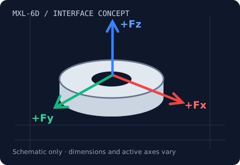
Review range & integration →MXL-6D · Fx, Fy, Fz, Mx, My, Mz
Measure three forces and three moments at one interface.
20 N–10 kN · 0.5–500 N·m family target
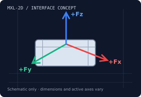
Review range & integration →MXL-2D · Fx & Fz, or Fx & Fy
Separate normal force from tangential friction force.
20 N–50 kN family target
Review range & integration →MXL-PLT · Aggregate Fx, Fy, Fz
Capture distributed forces across a rigid test surface.
5–200 kN per axis family target
Review range & integration →