
Only Fx, Fy and Fz?
A miniature three-axis load cell may fit a force-only fingertip measurement. Include local moments in the mechanical load review even when they are not measured.
Home / 6-Axis Load Cells / Miniature selection
MXL-6D / Fingertip & compact tooling
Specify the complete micro force/torque measurement package: six component ranges, tool-offset moments and a usable low-force signal.
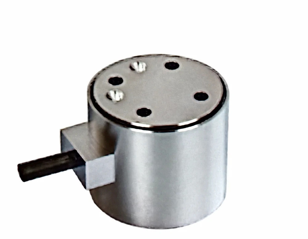
Start with the measured components
A micro six axis force torque sensor measures Fx, Fy, Fz and Mx, My, Mz about a defined origin. Its body diameter is only one selection constraint. Include mounting plates, screw engagement, cable movement and the external digitizer in the installed envelope.
| Request | Force target | Moment target | Reference for review | Next step |
|---|---|---|---|---|
| MXL-6D17 | Micro-force envelope by request | Micro-moment envelope by request | ATI Nano17 | Review MXL-6D17 |
| MXL-6D27 | Around 50 N requested | Around 1 N·m requested | Interface 6A27 / ME K6D27 | Review MXL-6D27 |
| MXL-6D40 | 20–500 N requested | 1–20 N·m requested | ATI Mini40 / Interface 6A40 | Review MXL-6D40 |
Dimensions, combined-load limits, crosstalk, overload, noise and environmental protection remain configuration approval items. For bulk sourcing, ask for quantity tiers, manufacturer verification and country-of-origin documentation with the configuration review.
A miniature three-axis load cell may fit a force-only fingertip measurement. Include local moments in the mechanical load review even when they are not measured.
Select a six-axis force/torque configuration. Define the moment origin and the contact offset before deciding whether a given force range is sufficient.
Compare the full six-axis family →Calculate your signed tool-offset load case →
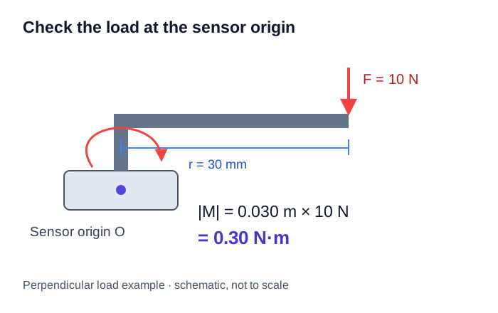
Worked load-path example
Assume a 10 N force perpendicular to a 30 mm tool offset. The applied moment at the sensor is 0.30 N·m, before adding tool weight, acceleration or other loads. This is a geometry example, not an MXL rated operating point.
|M| = |r × F| = 0.030 × 10 = 0.30 N·m
A tare command removes a signal offset; it does not remove the physical load or restore the mechanical overload margin. Use the sensor-origin wrench for the combined-load check and define the desired contact frame separately.
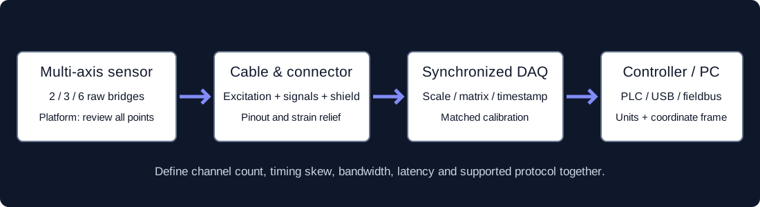
Reference: ATI DAQ manual, calibration matrix and tool-transformation sections. The manual links the matrix to the sensor serial number and distinguishes raw strain channels from resolved force/torque components.
Measure a useful signal
State the smallest force and moment change you need to distinguish, with units. Request measured RMS noise at the chosen sample rate and filter setting. ADC bit depth alone is insufficient.
Define sample rate, acquisition synchronization, effective bandwidth and end-to-end delay separately. A fast bus or sample clock does not by itself establish closed-loop performance.
Show the complete fingertip or tool assembly. Cable drag, mounting preload and a parasitic contact across the sensing structure can affect a low-force measurement.
Published reference / reviewed 31 October 2026
As a third-party reference, ATI lists the Nano17 at Ø17 mm × 14.5 mm with standard interface plates. Its SI-50-0.5 calibration lists Fx/Fy 50 N, Fz 70 N and moments of 500 N·mm, equivalent to 0.5 N·m. Those are ATI reference values, not approved MXL specifications.
Read the ATI Nano17 calibration and physical-specification tables. Verify the exact calibration, plate version and simultaneous-load graph rather than treating the model name as a complete specification.
Three force components can describe a resultant contact force. Add three measured moments when torsion, contact offset or a tool-center-point wrench is part of the measurement task. Both choices still need a combined-load review.
No. MXL identifiers describe requested configurations. An approved MXL drawing must establish the body, interface plates, connector and cable envelope. ATI reference dimensions describe the ATI product only.
Request a configuration review with six component ranges, simultaneous loads, envelope, noise and interface needs. MXL pricing, production capability and delivery are confirmed in the written quotation.
Include six peak loads, simultaneous loading, contact offset, minimum useful signal, envelope, bandwidth, quantity and receiving controller. Request the drawing and calibration scope with the sensor.