
One timing definition
Specify output rate, useful bandwidth, filter delay, timestamps, trigger or clock relationship and maximum acceptable inter-stream skew. A shared network interface alone does not prove simultaneous sampling.
Home / Products / Twelve-component sensing
MXL-12D / Engineering request family
Specify contact loading and motion together: three forces, three moments, three linear accelerations and three angular accelerations.
MXL-12D defines a request scope. Hardware, ranges, calibration and delivery are confirmed in a written offer.
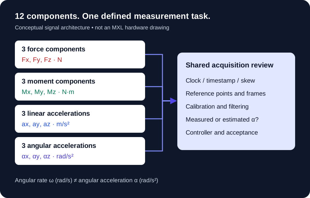
12 components / 4 physical quantities
Here, “12-axis force sensor” means a force/torque and acceleration system. Published twelve-component research combines a six-component wrench with linear and angular acceleration sensing. “12-DOF” is a term used in that literature; it does not add mechanical degrees of freedom to a rigid body. Read the research definition ↗
| Signal group | Three components | Units | Information needed for selection |
|---|---|---|---|
| Contact force | Fx, Fy, Fz | N | Separate shear and axial ranges, overload events and simultaneous load cases. |
| Moment | Mx, My, Mz | N·m | Define the sensor origin, tool offset and combined force/moment limits. |
| Linear acceleration | ax, ay, az | m/s² or g | State range, bandwidth, reference point, axis alignment and gravity/specific-force convention. |
| Angular acceleration | αx, αy, αz | rad/s² | State range and whether the output is measured or estimated; include estimator filtering and delay. |
Specify axis signs and the physical reference point for every signal. Unit strings in the RFQ are retained as entered; no automatic range conversion or hardware approval is performed.
Angular rate ≠ angular acceleration
A conventional six-DOF IMU can provide three accelerometer signals and three gyroscope rates. Angular velocity ω in rad/s is a different quantity from angular acceleration α in rad/s². The Bota driver documentation provides a concrete example of this distinction. Check the documented data fields ↗
If angular acceleration is estimated from rate, ask for the differentiation or observer method, useful bandwidth, noise and delay. Ask whether acceleration includes gravity and where the IMU sits relative to the force-sensor origin.
Also separate physical components from channel count. Four triaxial sensing points can use twelve raw channels in a platform; those channels do not provide the acceleration outputs defined above.
Review the distributed force-platform architecture →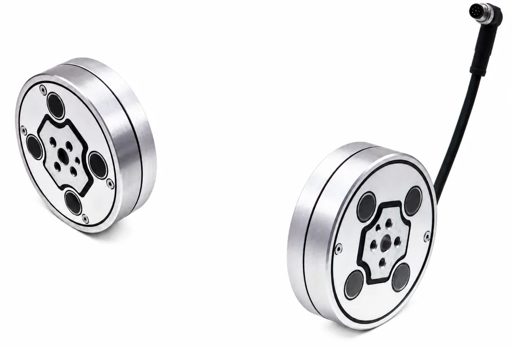
From signals to usable contact feedback
Specify output rate, useful bandwidth, filter delay, timestamps, trigger or clock relationship and maximum acceptable inter-stream skew. A shared network interface alone does not prove simultaneous sampling.
Identify the wrench origin, inertial reference point, sensor-to-tool alignment and the controller frame. Decide where coordinate and point transformations occur.
State tool mass, center of mass, inertia and motion conditions. Agree how gravity and motion contributions are separated from contact, and how the complete result is tested.
The Bota payload-processing reference requires known payload properties and measurements expressed in the same frame; it also identifies estimated angular acceleration. These are useful review questions, rather than evidence of an available MXL compensation implementation. Read the processing prerequisites ↗
Twelve-component acquisition can support compensation development, but it does not automatically provide corrected contact force, contact position or closed-loop stability. This page does not perform compensation or specify a safe controller.
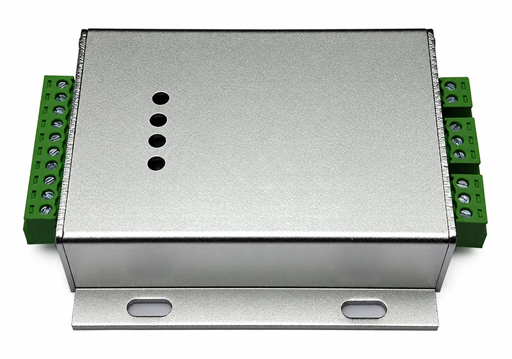
A bridge-only conditioner does not acquire angular acceleration by itself. Define the force transducer, inertial subsystem, conversion, synchronization and controller interface together.
The checklist is an engineering request worksheet, not a product datasheet. Requested interfaces and software support are confirmed for the proposed package.
For grinding, insertion or rapid tool motion, distinguish contact objectives from tool weight and motion loads. Start from the trajectory, tool model and controller timing.
Robot force-control requirements →Specify local forces and moments, inertial signal semantics, contact transitions and mounting stiffness. A sensor's output count alone does not establish balance or impact tolerance.
Review six-axis loads and tool offsets →A published space-manipulator implementation combines force/torque sensing, acceleration and acquisition. Its calibration and experiments are evidence of that research, not an MXL test result.
Read the 2017 ROBOT paper (PDF) ↗On this page, twelve-component means three forces, three moments, three linear accelerations and three angular accelerations. It does not mean twelve independent force directions. Confirm each output quantity and unit in the proposed system.
Check the IMU data fields. A typical accelerometer/gyroscope combination reports linear acceleration and angular rate. Rate in rad/s differs from angular acceleration in rad/s². A derived acceleration needs an explicit estimation method, filtering, timing and validation.
No. Separating payload motion effects from contact loading also requires a suitable model, mass, center of mass, inertia, coordinate alignment, timing and validated processing. Twelve available signals alone do not prove compensated contact-force accuracy.
Channel count and measured quantities are different. Four triaxial sensing points can produce twelve raw channels for an assembled force platform. Those channels do not, by themselves, measure linear or angular acceleration.
MXL-12D identifies an engineering request family. Send force, moment, both acceleration ranges, footprint and timing requirements. The supplied architecture, approved drawing, ranges, interface, calibration, software, price and delivery require a configuration-specific written offer.
Request the applicable force/torque calibration and frame definition, inertial scale and alignment records, angular-acceleration method, timing characterization and acceptance tests for the complete assembly. A six-axis calibration matrix alone does not establish the performance of the other signals.
Technical basis / reviewed 2026-11-01
These primary sources explain architectures and measurement semantics. Their ranges, algorithms, results and software support are not MXL specifications.
Journal of Sensors, 2017, DOI 10.1155/2017/2836365. Supports the force/torque plus linear/angular acceleration architecture and coupling discussion; research results are not MXL specifications.
ROBOT 39(3), 2017, DOI 10.13973/j.cnki.robot.2017.0257. A research implementation combining force/torque, acceleration and acquisition; its hardware and experimental outcomes describe that research only.
The documented IMU fields contain linear acceleration and angular rate. This is a reference example of signal semantics, not MXL software or interface support.
Defines common-frame and payload mass, center-of-mass and inertia prerequisites; angular acceleration can be estimated from angular velocity in that implementation. No MXL compensation package is implied.
MXL-12D / Your engineering request
Include force and moment ranges, both acceleration ranges and timing requirements. Production integration, approved drawings, calibration scope, pricing and delivery remain subject to the written offer.